The Toolpath
In computer-aided manufacturing, a toolpath refers to a sequence of movement instructions to an end effector. In extrusion-based 3D printing, the toolpath is the trajectory of the extruder on a robotic arm or gantry.
Toolpath data structure
Ovenbird adopts the classic layer-based toolpath data structure where each Toolpath contains a sequence of planar layers, and each layer contains one or multiple planar curves. (1)
The following table compares an Ovenbird 
Toolpath with a toolpath from a conventional slicing software for fused desposition modelling (FDM) printers. (2)
-
Example File
1. Introduction → (1) Toolpath and Continuous Toolpath - Ovenbird does not support non-planar layers, variable extrusion width, or branches with different layer counts.
| Conventional toolpath | Ovenbird Toolpath | |
|---|---|---|
| Curve sources | Parallel slicing | Adaptive parallel/rotary slicing, Custom slicing, Native curves |
| Layer relations | Parallel | Parallel or non-parallel |
| Layer thickness | Pre-determined, uniform | Adaptive, uniform or variable |
Comparison between toolpath data structures
The IO column explains in detail how curves are organized and accessed.
The Ovenbird framework
The Toolpath is the core of the Ovenbird framework. The following image shows how it incorporates optimization/modification methods and pipelines different data types and purposes.
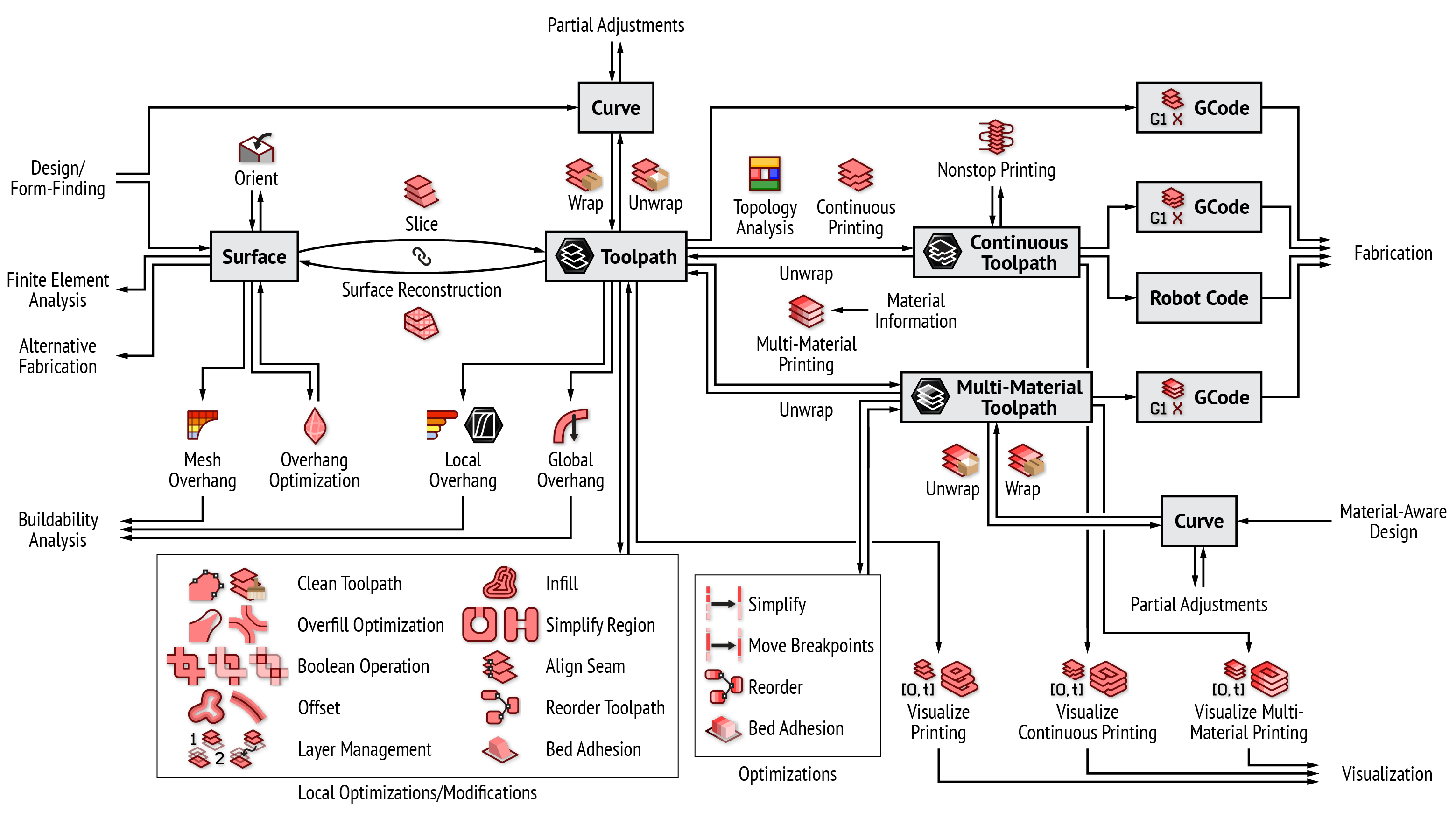
The Ovenbird framework
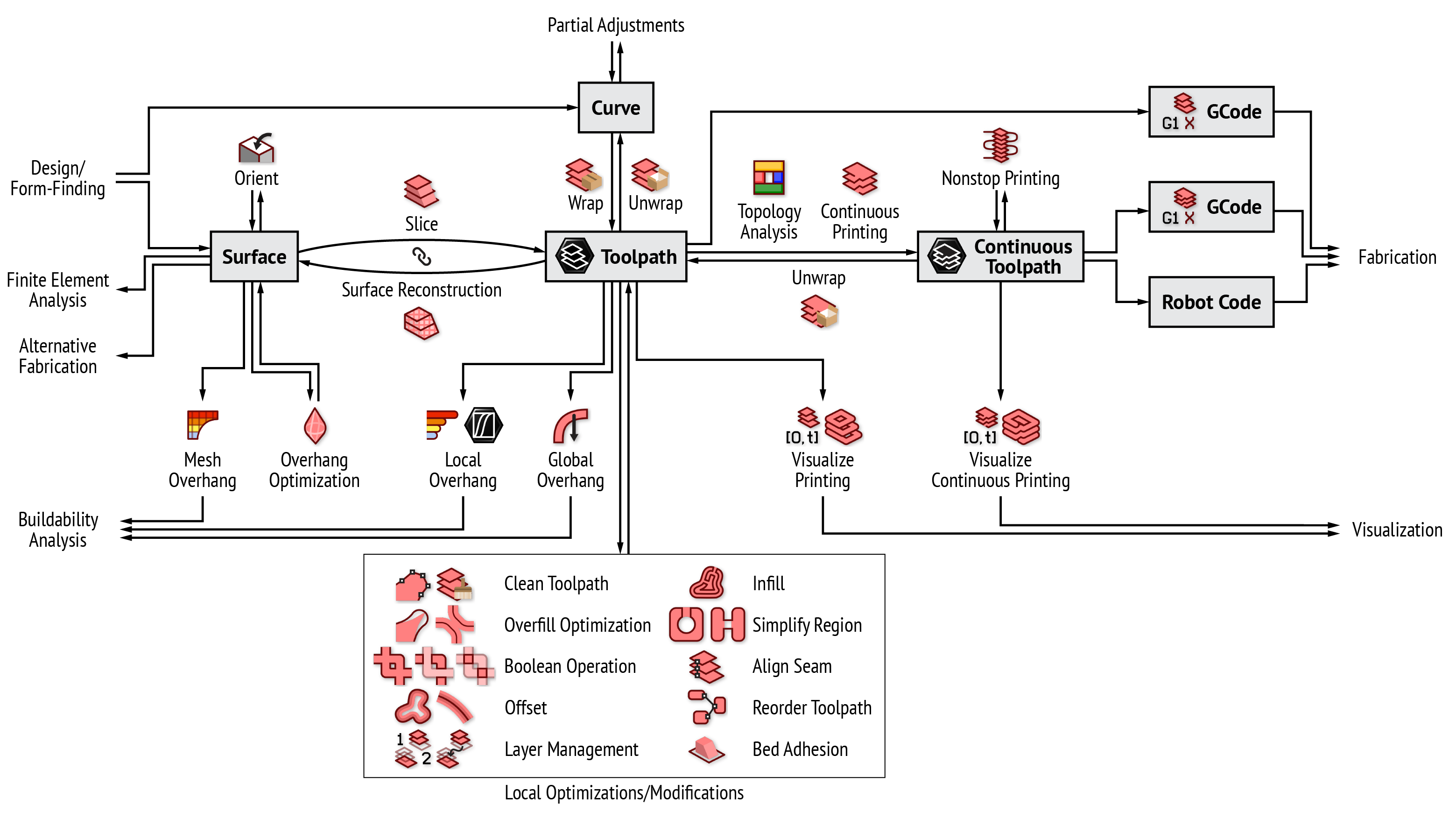
The Ovenbird framework (single-material only)