Visualization
Visualization Mesh

Visualize Printing and 
Visualize Continuous Printing converts toolpath curves into visualization meshes. Each curve produces one clean, closed mesh, organized in sections (and caps if the curve is open). You may change the subdivision level to adjust the quality and size of the meshes.
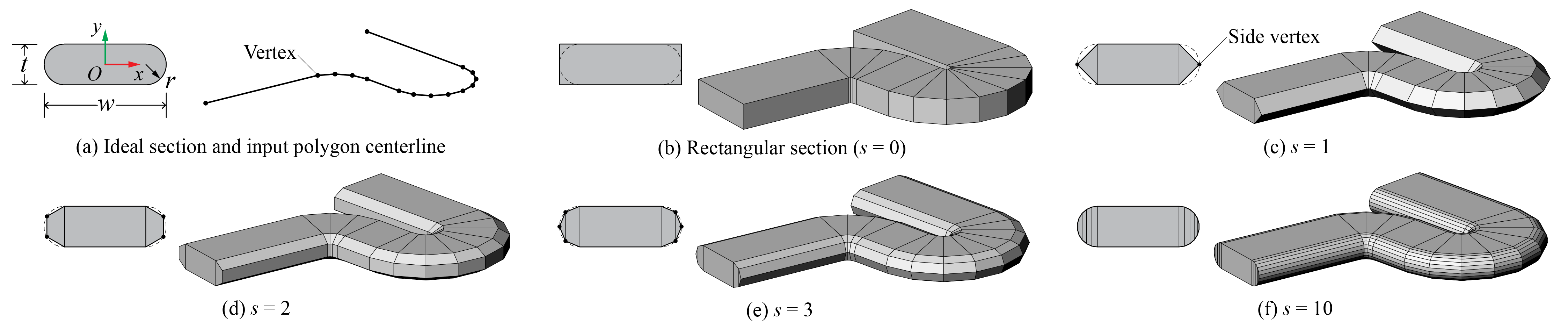
Sectional shape of the visualization mesh, showing the effect of subdivision (1)
- Image adapted from: Y. Zhi, H. Chai, T. Teng, and M. Akbarzadeh, “Automated toolpath design of 3D concrete printing structural components,” Additive Manufacturing, p. 104662, 2025.
To finetune the density of sections in the visualization meshes, use 
Polyline Toolpath
Effect of changing the polyline resolution and mesh subdivision
The sections are placed at the bisecting planes of adjacent segments. There are two ways to determine the width of the sections.
-
The corner width method uses a consistent width for sections. However, it results in long, thin segments.
-
The segment width method widens the sections such that each segment is consistently wide. However, it creates long spikes at sharp turning points.
We suggest to, and by default, use the corner width method with fillet points added to long segments such that both the segments and corners look clean.
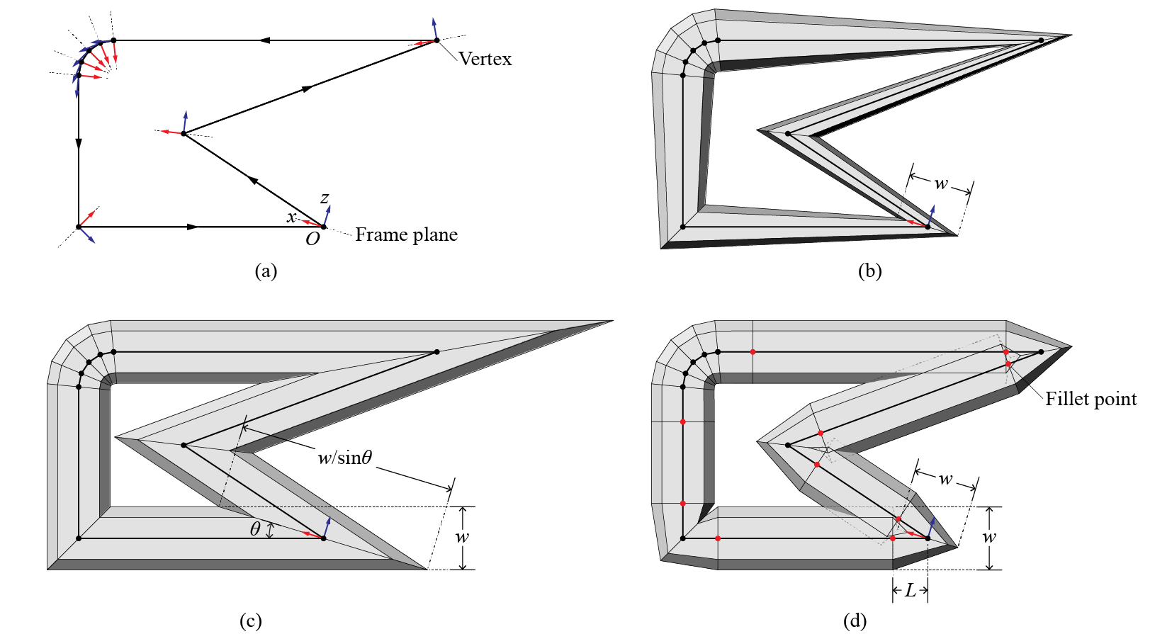
Methods of determining sections. (a) Toolpath polygon and frame planes; (b) corner width method; (c) segment width method; (d) corner width method with fillet points (1)
- Image adapted from: Y. Zhi, H. Chai, T. Teng, and M. Akbarzadeh, “Automated toolpath design of 3D concrete printing structural components,” Additive Manufacturing, p. 104662, 2025.
Example Files
7. IO and Visualization → (3) Toolpath Visualization
7. IO and Visualization → (4) Toolpath Visualization In Place
7. IO and Visualization → (5) Corner Width and Segment Width
Animation
Using a parameter \(t\in[0,1]\), 
Sub Toolpath and 
Sub Continuous Toolpath extract the beginnig part \([0,t]\) of a Toolpath/Continuous Toolpath. When connected to visualization components, they produce printing animations.
Animation of continuous printing created by Sub Continuous Toolpath and Visualize Continuous Printing (1)
-
Example File
3. Toolpath Operations → (5) Infill and Split Layers